From Scratch to Wind Tunnel: Building an Anemometer in One Week
The Challenge
As part of my second year of Industrial Engineering at the Vrije Universiteit Brussel (VUB), we have a course called Ontwerpproject (Engineering Design Project).
Throughout the academic year, we work on three different projects, each focusing on different engineering skills. The first project lasts one week, the second two weeks, and the final project three weeks. During these project weeks, our regular classes are completely suspended, allowing us to focus entirely on designing, building, and testing our creations.
Our first challenge? Design and build a fully functional anemometer in just five days.
An anemometer is a device used to measure wind speed. Sounds simple enough, right? Well, there was a little more to it. For the most part fun!!
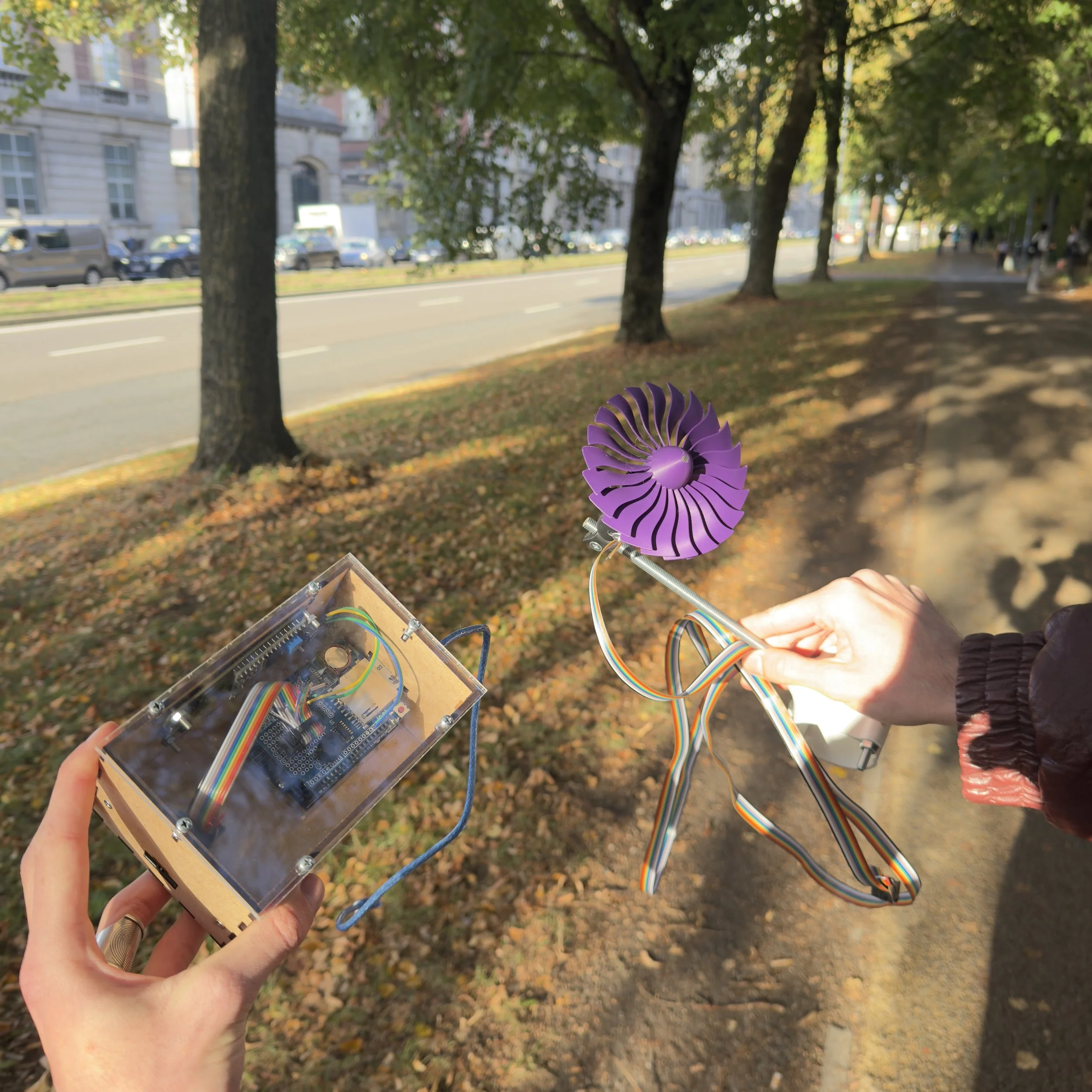
Working in a team of three, we had to design and manufacture the mechanical components, develop the electronics, program an Arduino to measure rotational speed, and convert those measurements into accurate wind speed readings. On top of that, our device needed to display the measurements on an LCD, log data to an SD card, and ultimately prove its accuracy in a professional wind tunnel.
All of this had to come together in just one week, from the very first CAD model to a working physical device.
And that's exactly what made this project so exciting. We weren't just following instructions to assemble something. We were given a challenge, a set of requirements, and the freedom to figure out how to make it work.
From idea to Reality
Instead of designing the entire anemometer upfront, we took a more hands-on approach. We designed and manufactured a few components at a time, tested how they worked, and made adjustments whenever something didn't quite fit or behave as expected.
It was a constant cycle of designing, 3D printing, assembling, testing, and tweaking. Sometimes a part worked perfectly on the first try, while other times we had to go back into CAD and make a few changes.
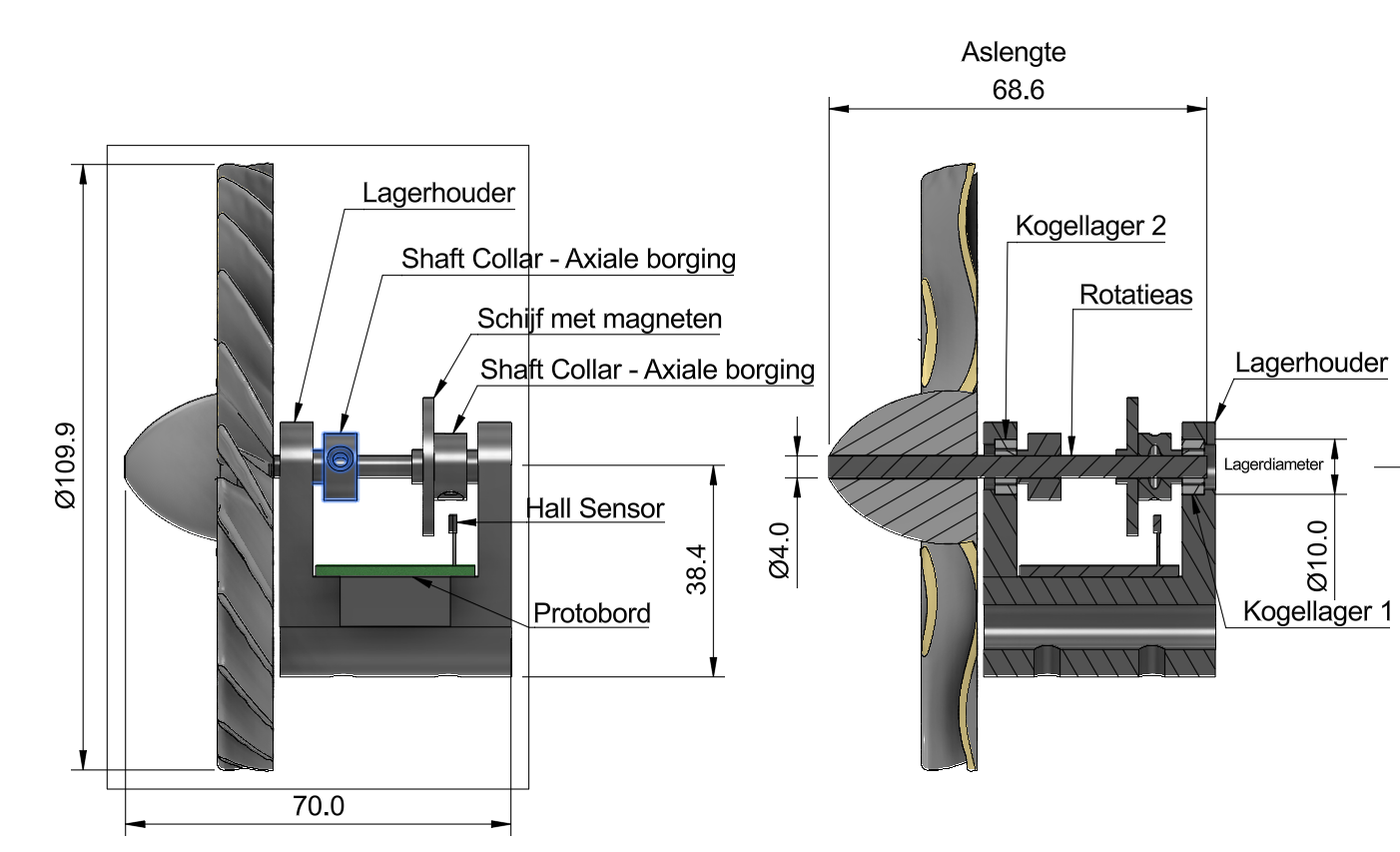
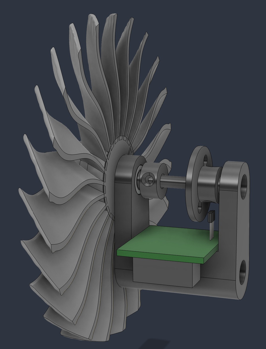
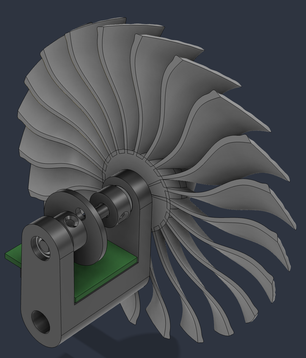
I took on most of the technical development, combining mechanical design, electronics, and programming. On the mechanical side, I used Fusion360 to design the individual 3D-printed components, including the rotor and the parts supporting the rotating shaft and bearings. Getting everything to fit together while keeping friction as low as possible was an important part of the process.
On the electronics side, I worked on integrating the Hall-effect sensor with the Arduino, allowing us to detect the rotor's revolutions and calculate its RPM. I also developed the Arduino code to process these measurements, convert them into wind speed readings, display the results on an LCD, and log the data to an SD card.
Meanwhile, my two teammates worked on soldering, laser cutting, documentation, CAD, and the design of the controller enclosure, which turned out looking amazing. Everyone had their own responsibilities, but we regularly helped each other out and worked through challenges together.
I particularly enjoyed taking the lead on the technical side of the project. Having previous experience with CAD, 3D printing, and electronics allowed me to share what I knew, help my teammates, and coordinate the different parts of the build.
Towards the end of the week, once we had settled on our final components, I created a complete CAD assembly based on the parts we had actually manufactured and used. I also prepared the technical drawings, documenting the finished mechanical design and how everything fitted together.
Seeing all those individual components turn into a fully functioning device was incredibly satisfying.
And the best part? We weren't just building something that looked good. It actually had to work.
Putting It to the Test
Of course, building the anemometer was only half the challenge. We also had to make sure it could actually measure wind speed accurately.
To do this, we first tested our anemometer in the smaller wind tunnel at the VUB Fablab. By comparing the rotational speed of our rotor (RPM) with the reference wind speed, we collected calibration data and plotted a graph to establish the relationship between the two.
This allowed us to convert the rotor's RPM into actual wind speed measurements through our Arduino code.
The next day, we got the opportunity to test our creation in a much larger, professional wind tunnel. And honestly, that was one of the coolest moments of the entire week.
Seeing something we had designed and built ourselves spinning inside such an impressive piece of engineering equipment was incredibly satisfying.
Even better, our initial calibration turned out to be surprisingly accurate! When comparing our measurements with the reference values in the large wind tunnel, we were only about 0.1 to 0.2 m/s off during those preliminary tests.
We also pushed the wind speed all the way up to 16.6 m/s, and watching our 3D-printed rotor spin so smoothly and remain stable at those speeds was amazing.
After spending days designing, printing, wiring, programming, and adjusting everything, seeing it perform that well was such a rewarding moment.
At that point, we still had our final graded wind tunnel test ahead of us, but those first results already gave us a lot of confidence in what we had built.
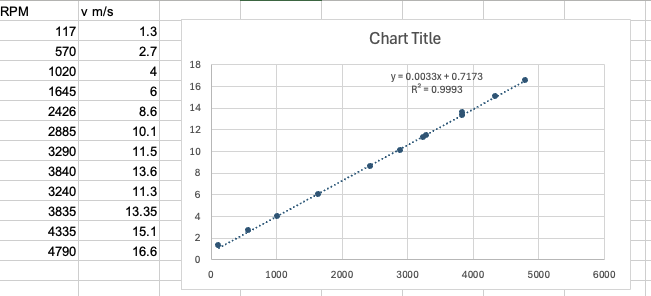
This is the graph that came out of the fist calibration run in the big VUB wind tunnel
Looking Back
What I enjoyed most about this project was the freedom to create something from scratch, but with strict guidelines. We started the week with a challenge and a collection of components, and just a few days later, we had built an actual working wind measurement system.
It was also really cool to see so many different engineering disciplines come together in one project. Mechanical design, 3D printing, electronics, programming, and data analysis all had to work together. Getting one part right wasn't enough; everything had to function as a complete system.
Another highlight for me was the teamwork. I really enjoyed taking responsibility, sharing my experience, and helping the others whenever I could. Everyone contributed in their own way, and I think we worked really well together throughout the week.
What made this project especially fun was that we weren't just learning about engineering concepts in a classroom. We were actually applying them, running into real problems, figuring out solutions, and seeing the results of our decisions almost immediately.
This was the second time where I would spend the whole week in the VUB’s FabLab. When everyone is working on their project against the clock, it creates an incredibly cool atmosphere. I’m eagerly looking forward to the next projects.
And honestly, there's something incredibly satisfying about watching a device you designed and built yourself do exactly what it's supposed to do.
Our final wind tunnel evaluation is still ahead of us, but regardless of the score, this has already been one of the most enjoyable weeks of my engineering studies so far.
From an idea to a working anemometer in just one week. Pretty awesome!